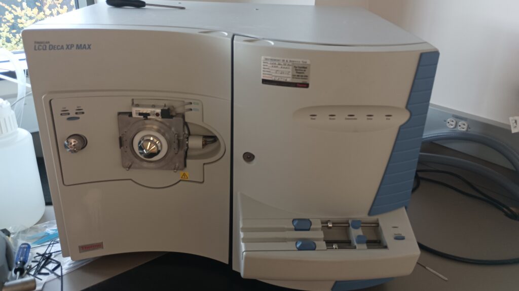
The CMS has a Thermo Finnegan LCQ Deca XP Max used before the purchase of the Q Exactive HF-X in 2017. It is a linear ion trap instrument that can achieve only 4% the resolution possible on the QE HF-X and is significantly less sensitive. However the LCQ is a robust instrument with much lower gas consumption rates and is thus suitable as a general purpose and teaching instrument.
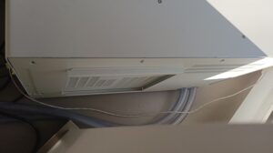
After a five year shutdown the instrument was cautiously restarted to identify components requiring service or replacement. Several issues were immediately identified. Cooling fans ran intermittently and were squeaking and clipping and the acquisition PC display did not work. This was traced back to a seized cooling fan and bulging capacitors in the graphics card. Fortunately removal of the graphics card allowed use of the integrated GPU. Instrument manager was not started by the PC and thus the tune page was unusable At this point the instrument was identified through the Ethernet data connection and data could be sent, however none was received.
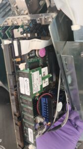
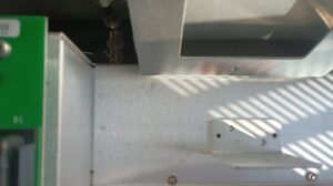
This first step was to restore communication with the instrument and a failure of the CMOS battery in the onboard instrument PC was suspected as this can result in BIOS errors during startup. Fortunately the LCQ onboard PC has VGA display and PS2 keyboard ports for diagnostics. To access these ports the instrument must be opened using by first loosening the large black bolt on the front of the instrument.
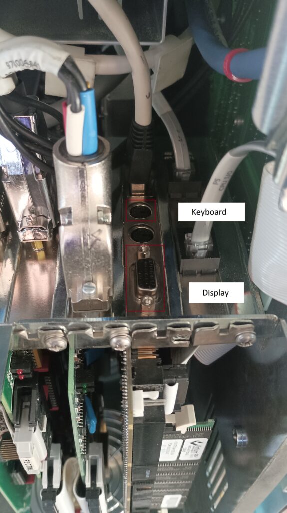
With the instrument doors open the PC panel can be removed by unscrewing the panel cover on the right side. This is not required to connect the display and keyboard but is a good idea so the CPU fan can be checked as they have been known to seize in some instruments.
The keyboard and display ports are on the top of the panel. A PS2 mouse connector is in between them but is not usable.
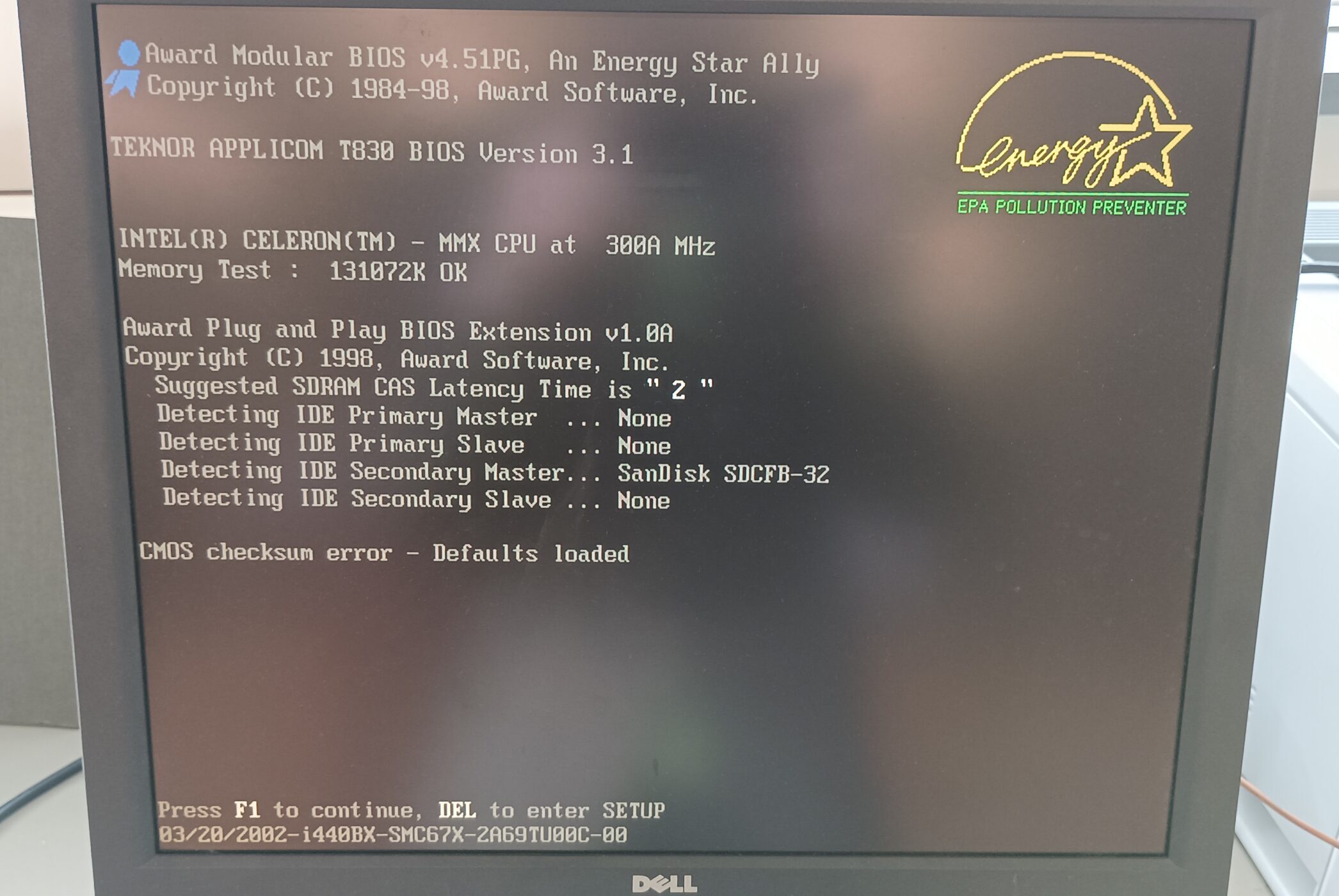
 The PC booted but a CMOS battery failure error occurred. This following error was the reason for lack of communication with the instrument and can be bypassed by pressing F1 on the keyboard.
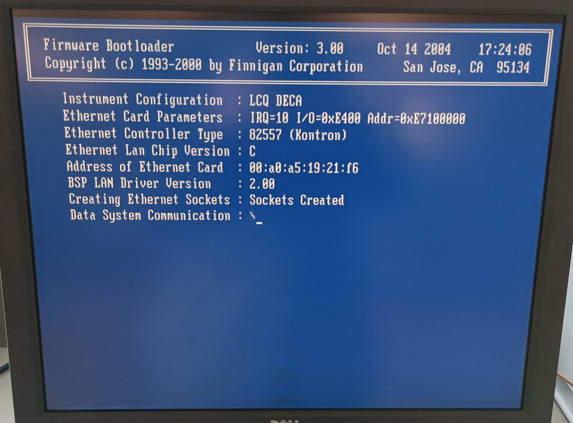
The instrument booted successfully and communication was restored. Rebooting may need to be attempted several times with the analysis PC on or off until instrument manager starts automatically.
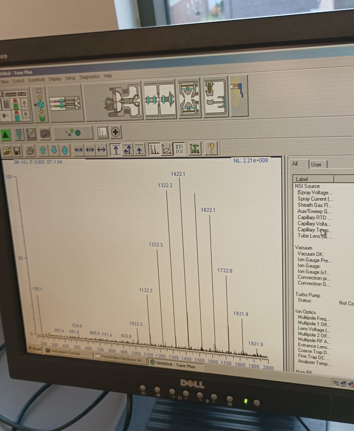
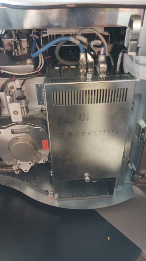
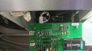
The instrument was run for an hour to pump down before acquiring acceptable MS spectra with calibrant solution. The instrument was vented for to address the fan issues which we now knew were worth fixing as the instrument still functioned. The CMOS battery is a TL-5186 battery (the purple disk in the following image) and replacements are available, however it may be soldered to the board and the risk involved in changing it seems higher than keeping a keyboard connected to the motherboard for the rare times when the instrument is vented. The CPU fan spun freely but could be replaced as a precaution however this requires removing the CPU heat sink which was similarly avoided.
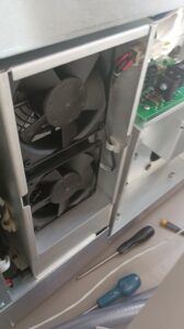
There are five 120 mm cooling fans in the LCQ, two intake fans for the MS electronics, two exhaust fans for the turbomolecular pump and other vacuum chamber components, and one for the onboard PC. The onboard PC fan can be removed by unscrewing or unbolting the fittings on the bottom of the enclosure. These bolts are difficult to access and removing the black connector on the right side may be required to access one of the screw. Once the fan is free it can be disconnected by pulling out the black two pin plug on the fan body. The fans must be installed facing the same direction so it is best to keep notes.
Next the MS electronics and vacuum system fans can be removed by screwing the back housing plate
With these removed and the plate slid out the upper left side electronics cooling fans can be unscrewed.
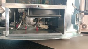
Next the vacuum exhaust fans must be removed. This is more difficult as they are mounted on the inside of a removable chassis. First the catch screws (seen in the right side of the previous photo) on the bottom of this unit are removed. The chassis can then be slid out so the electronics connections can be removed. I disconnected the left and right BNC cables first.
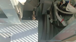
Next the molex connectors to this PCB can be removed.
Finally the black plugs on the fan can be removed and the chassis removed for further work. The fans can easily be unscrewed at this point.
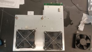
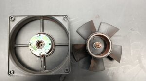
Now with all the fans removed they were spun to see which ones had bad bearings. The exhaust fans and PC cooling fans were partially or completely seized, leading to the sounds noted earlier. Rust and white mold was visible on the exterior of some fans. The exhaust and PC bearings may have gone bad first either due to condensation as they are in areas where air is cooling down (as evidenced by mold growth), or because the higher temperatures they are exposed to degraded their lubricant. These are ebmpapst 4394 fans and replacements are still available but are fairly expensive at ~$60 each and unfortunately the plug connectors are uncommon. Instead the fan bearings (twenty replacement 624ZZ bearings are available for under $20 on Amazon at the time of writing) were replaced as the motors seemed to be in good condition. I opted to change the bearings on all the fans (ten bearings total) instead of just those that had seized. 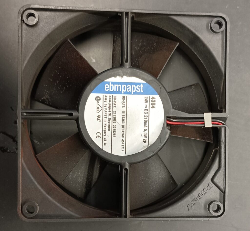
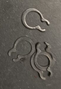
After removing the stickers on the fans I large amounts of rust could be seen and the retaining clip on one fan had completely disintegrated.
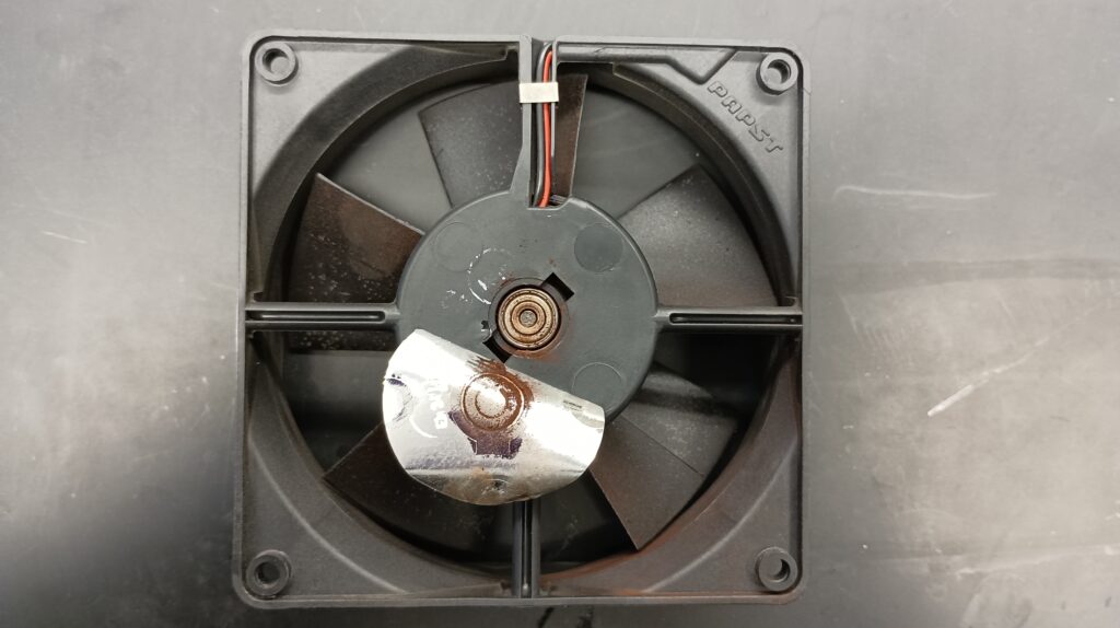
The retaining clips on the shaft can be removed with pliers and the blades slide out.
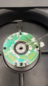
The bearings can be removed by inserting a punch or screwdriver through each side and pushing them out from the back. The fan blades and motor housing was cleaned with a damp cloth and dried to remove debris that might shorten the life of the replacement bearings. The new bearings can be gently inserted into the holes and a very small drop of lubricating oil added.
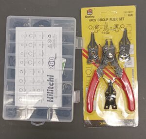
The fan blade and shaft can be slid back into the bearings. If the spring between the bearings and blades was removed during cleaning make sure to replace it first. Now new 4 mm retaining clips can be put on the shaft. I ordered a pack with many different sizes and a tool for around $20 however the latter was not needed for these small clips.
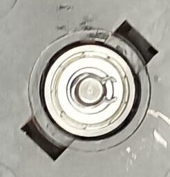
The retaining rings can be gently pressed onto the shaft with fingers or pliers and rotated to ensure they properly seat in the groove.
Finally the fans were checked to ensure they spun freely and that there was minimal play in the rotor. The instrument was then reassembled and calibrant solution used to verify instrument functionality. The cost of refurbishing the fans and restoring the instrument to an operational state was under $50.