By Cindy Li, Engineering ’18
Currently SAL conducts unmanned aerial photogrammetric surveying with the DJI Phantom 4 and its onboard 4K Camera. The SAL wants to expand its mapping capabilities to include infrared imaging with the Mobius Infrared Action Cam. I am currently working creating a 3D printed mount that can be externally attached to the drone. For the CAD moels, I used Onshape, a cloud based 3D modeling software and 3D printed three iterations of Prototype Design A using the Ultimaker 3 Extended.
The design requirements (DRs) of the mount are:
- Lightweight so the flight time of the drone is not significantly decreased from the additional load
- Securely attach the Mobius Camera to the drone
- Enable access to the buttons of the camera
Prototypes #A1
The first prototype I created is A1. The center cutout is to house the Mobius Cam. The middle cutouts are to reduce the overall weight of the mount. The end two cutouts are used to ziptie the mount between the legs of the drone in the back, out of the way of the onboard 4K camera.
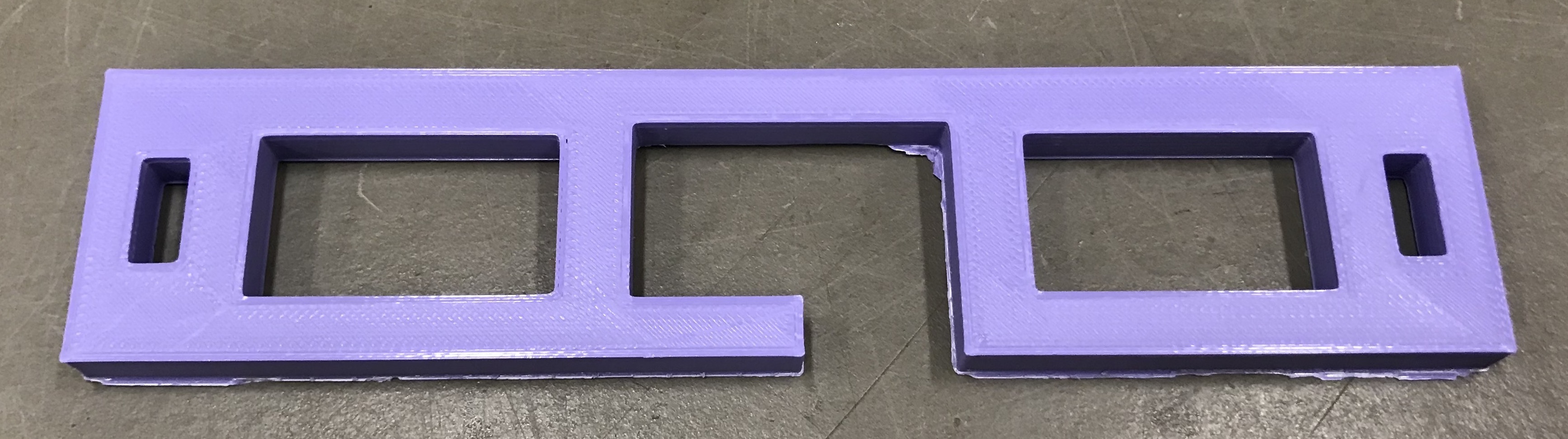
Figure 1. 3D print of A1
Printing time: ~2 hrs
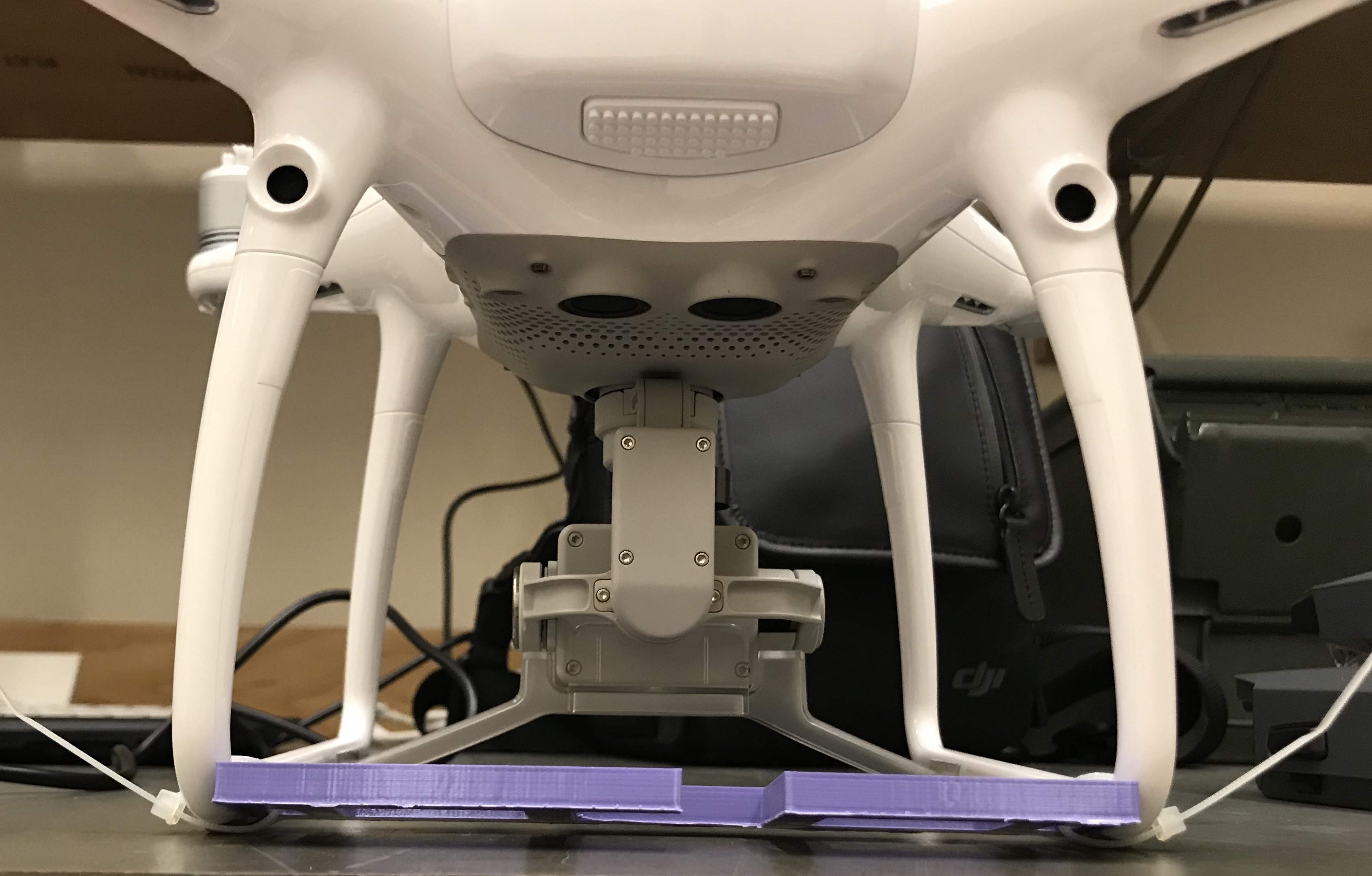
Figure 2. Front view of the A1 attached to the back of the DJI Phantom 4.
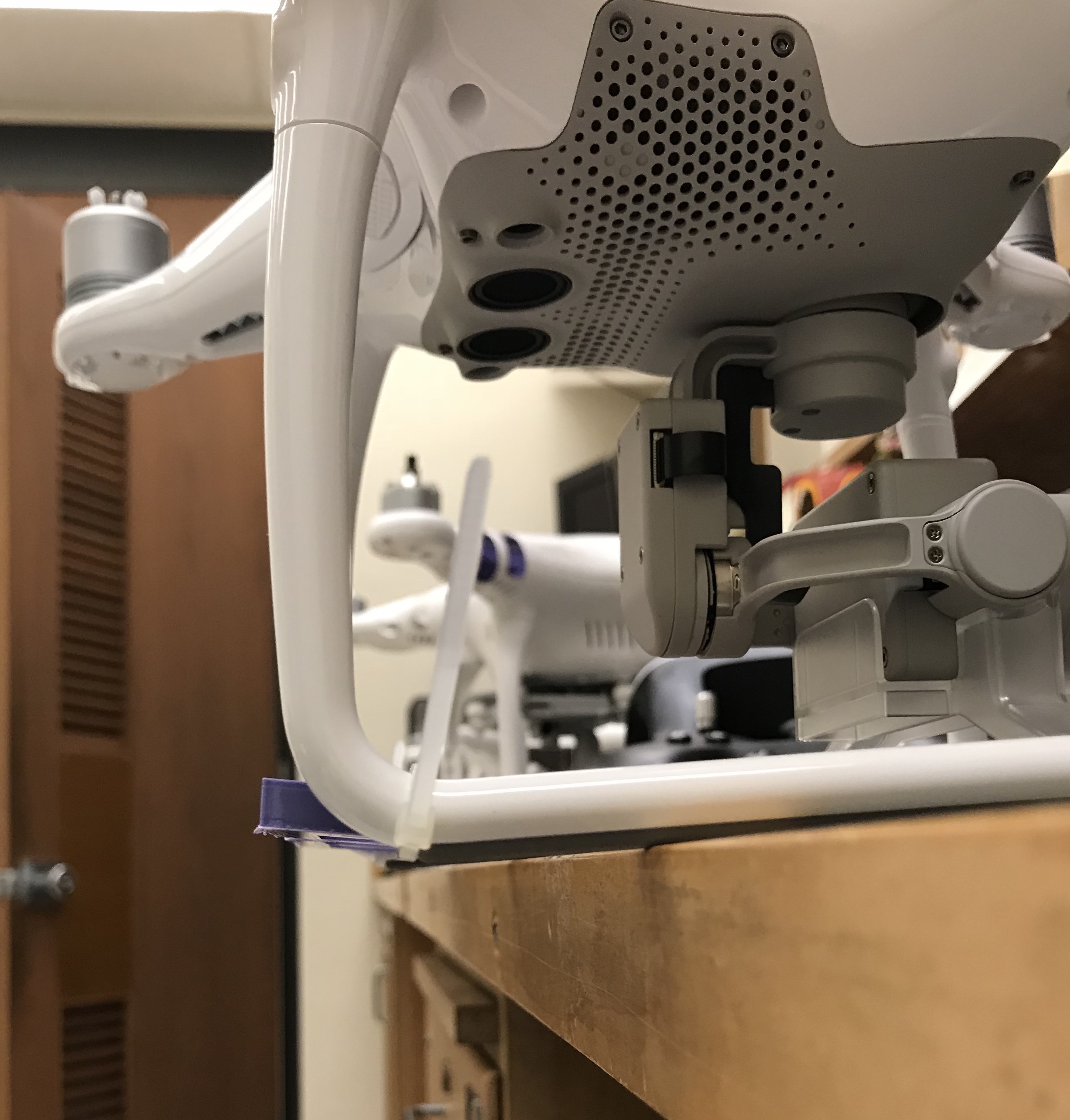
Figure 3. Side view of A1 ziptied to the back legs.
Improvements for A1:
- Decrease the thickness of the mount walls to reduce overall weight and 3D printing time. The A1 took ~2 hrs to print.
- The PLA plastic (for 3D printing) was a lot stronger than I thought so decreasing the overall thickness should not decrease the structural integrity of the mount
- When attached with zip ties to the DJI:
- The mount was too short for the span of the bottom legs and this caused uneven tightening of the zipties.
- The mount will not sit flush again the bottom of the legs and experiences rotation in the z-axis as seen in Figure 2 & 3. This is caused by the large size of the ziptie cut out holes.
- How to stabilize the mount from the ziptie attachments?
Prototype #A2
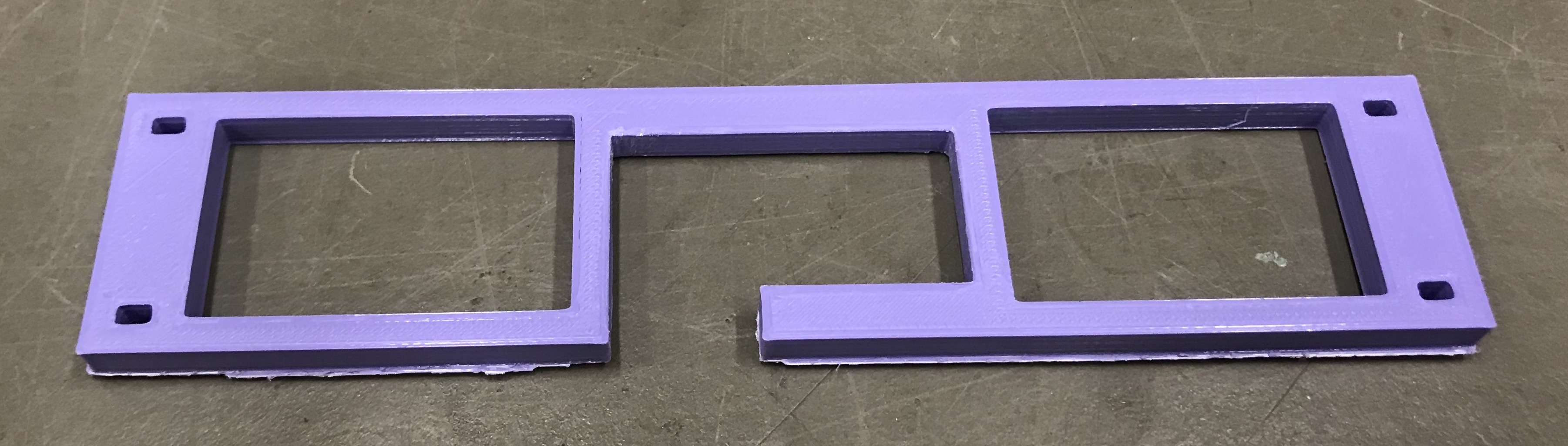
Figure 4. 3D print of A2.
Printing time: 1.5 hrs
Design Changes
- Cut printing time down to 1.5 hrs by decreasing the overall thickness to 0.2 inches.
- The length of the mount increased by 1/8th to 5.686 inches to improve fit of Cam.
- Increase the ziptie holes from one to two on each side for improved stability
Improvements for #A2
- Ziplines holes were too small
- If holes are rotated 90 degrees, the zipties should be able to fit
- To avoid overcomplicating how to achieve a secure fit of the Mobius Cam in the mount, accurate measurements the Mobius camera are needed and the cam will hopefully slide into place
- The space left for the buttons on the camera caused the mount to be prone to bending and weakens overall structure
Prototype #A3
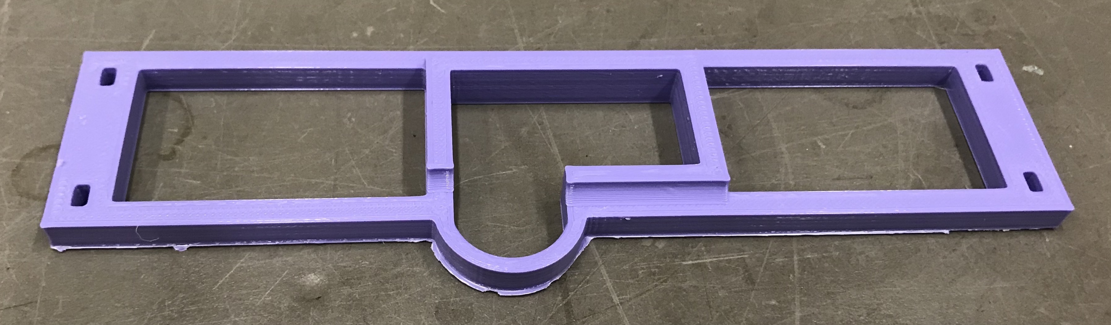
Figure 5. 3D print of A3.
Printing time: still 1.5 hrs
Design Changes
- Center of Design and Fabrication on campus was able to use precise calipers to obtain accurate measurements of the Mobius Cam.
- Ziptie holes were repositioned for better fit.
- This change also enabled larger middle cutouts allowing a slight decrease in overall weight, but no significant changes to print time.
- An arc was added to the front of the mount for easy access to buttons on the campus and structure support when in flight.
- Shelf was added to the location of the camera (in the center of the mount) to keep the camera pointing straight down.
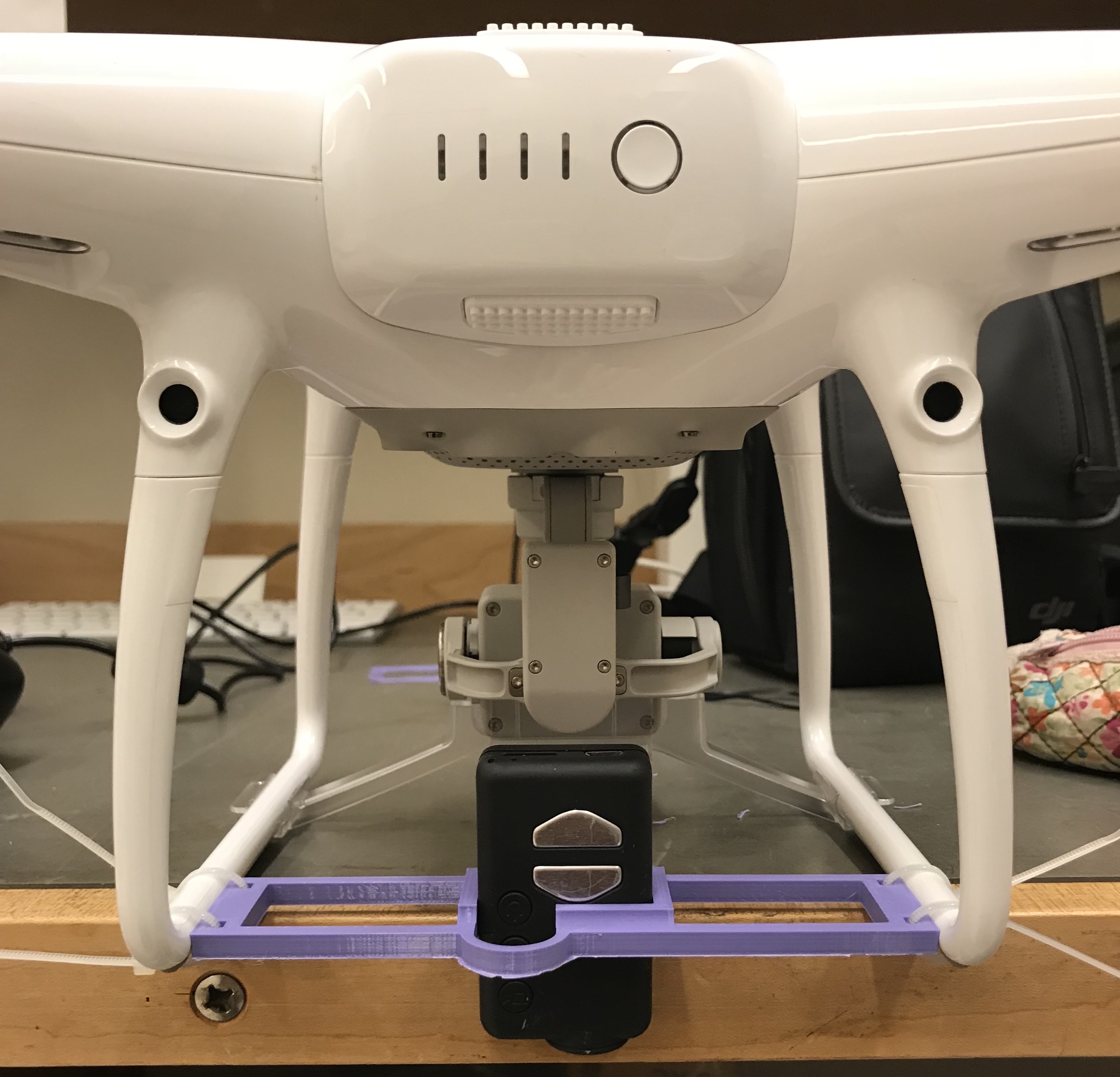
Figure 6. Mobius Cam pointed downwards & mount attached to the drone.
Comments on #A3 Design
- The arc provides functional structure support because there is ample space for easy access to the buttons on the Mobius Cam, even for big fingers.
- The width measurement of the Cam cutout is very precise and creates a secure fit
- If there were any surface stickers on the Cam, the Cam would not slide in easily, so identification stickers should be positioned on the top or bottom of the Cam.
- The tightness of the fit causes slight scratching on the rubber coating of the Cam. A chamfer could be added to the inside corner of under the silver buttons to mitigate this issue. But after a conversation with my supervisor, it is not a concern that needs to become a design requirement.
Prototype A ended at A3 because a fourth design requirement (DR) was added: to have the camera be able to capture imagery when the camera is positioned upwards and downwards in the mount. Prototype A fails to meet this DR, because when the camera is pointed upwards, from its current location, the body of the drone blocks its field of vision.