Lab #13 (05/02/02)
Input/Output operations with 3-state drivers (input AND output today!)
© D. Thiébaut
![]() CSC270
Lab #13
CSC270
Lab #13
Experiment #1: Input/Output with a flip-flop and a switch

Today you will implement a 1-bit input and a 1-bit output.
1-BIT OUTPUT
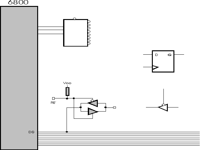
First, implement the 1-bit output. Connect the output of the flipflop to an LED. Add the missing details to Figure 1 above and test your circuit. Use as much or as little of Lab 12 as you need/want.
When the output bit works, implement the input bit. You do not need to implement the debouncing RS flip-flop for this lab.
The figure above shows the tristate driver as a non-inverting buffer with an active-low output. Not all drivers work this way. We have available many tristate drivers, and it is up to you to select the one you think will fit your design best. Some of them are inverters, some of them have active low enables, while others have active-high enables. Some even have two kinds of enables, one low and one high.
Here is the list of what is available:
Make sure you carefully check the implementation of the RE' (Read-Enable bar) signal, as well as the implementation of the enable of the tri-state driver (which might be active low or high, depending on the circuit you are using.)
To test your circuit, write a simple infinite loop that reads the 1-Bit input, and puts it out to the LED through the 1-bit output. Connect the input of the tri-state driver to a manual switch (DIP switch at the bottom left of the kit). Verify that when you activate the switch, the LED changes state.
Experiment #2: Software variation.
-
Modify your program so that the LED blinks ON and OFF at a visible rate
when the switch is OFF, and stays lit when the switch is ON.
Experiment #3: Two bits of I/O.
Add another input switch and another output flipflop.
This addition should be almost free as you already have the second flipflop on the breadboard, and you have 8 tristate drivers on the kit and 8 in the circuit you already selected.
To test your circuit, write another simple infinite loop that reads the status of the 2 bits and displays their values on the two LEDs.
When this test program works, create a new one where the behavior of the flipflops will be as follows: