Biological Sciences 300, Smith College | Neurophysiology
Lab 4: Action Potentials in Earthworm Giant Axons
http://www.science.smith.edu/departments/NeuroSci/courses/bio330/labs/L4giants.html
Bio 300 Home | Schedule | Laboratories | Administrative Information
An older version of this lab exists, where hook electrodes are used for recording.
View the video: Action Potentials in Earthworm Giant Axons
Equipment:
- Oscilloscope and audio monitor
- Preamplifier
- Stimulator with twin-pulse capability, pin electrodes, synch cable
- Dissecting microscope
- Micromanipulator and suction electrodes
- Shallow dissecting dish
- Earthworm saline in squeeze bottles
- Glass probe, cm ruler, dissecting tools
1. Background.
Giant axons
Many invertebrates have evolved giant axons for rapid
conduction of action potentials, typically as part of
circuits mediating rapid escape reflexes. The squid's giant
axon is the best-known example, but the earthworm's giant
axons have also been studied extensively, and earthworms
have the advantage of being relatively easy to keep in the
lab. We will make extracellular recordings from the giant
fibers, which will enable us to observe many of the
important aspects of action potentials. The experiment is
adapted from Welsh, Smith & Kammer, Laboratory
Exercises in Invertebrate Physiology, pp. 139-141.
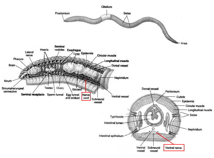
Micrographs of Lumbriculus variegatus by Alanna Morris, from a project in Bio 337, Fine Structure. The region in the red rectangle, the ventral nerve cord, is enlarged at the right. gf, giant fibers; np, neuropile.
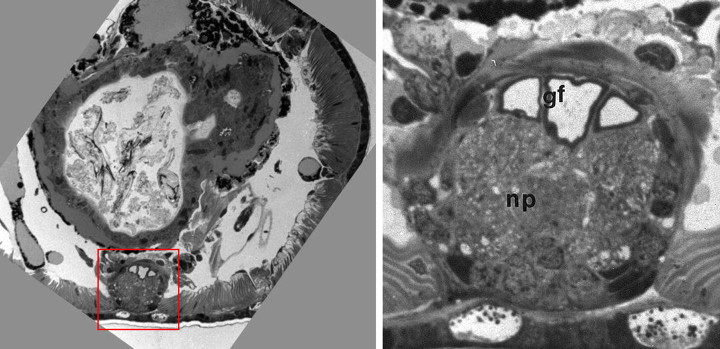
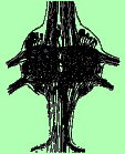
An annelid worm's nerve cord is near the ventral surface of the worm, at the bottom in the cross-section on the left. (The large structure that fills most of the body cavity is the intestine.) The giant axons appear as three large profiles (gf) near the dorsal surface of the cord, seen better in the close-up figure. The median giant axon in the center is larger (and conducts more rapidly) than the two lateral giants next to it. The remainder of the nerve cord is largely neuropile (np), where synaptic connections are made. Profiles of ordinary-sized axons can also be seen, and a few neuronal cell bodies appear around the periphery.
Each giant axon is formed from many individual neurons whose axons fuse into a single functional unit, but whose cell bodies remain separate. In addition, the two lateral giants are interconnected by electrical synapses at many points along their lengths and normally fire together. (They jointly contribute only one spike to an extracellular record.) In mediating the startle response, the median giant receives sensory input from the anterior end of the worm, and the laterals from the posterior, so that normally the median and laterals conduct in opposite directions. However, when action potentials are electrically stimulated (as in our experiment), the spikes propagate away from the stimulating electrodes in both directions.
Extracellular recording of action potentials
A microelectrode inside a neuron detects an action potential as a positive-going change from the negative resting potential. The size of the spike, from resting potential to its peak, is about 100 mV. In today's experiments, we will use an extracellular suction electrode that detects the local circuit currents flowing around an axon as the action potential propagates. The change in potential detected by the electrode is much smaller, about 1 mV for spikes in giant axons and as small as a few µV for small axons. As a result, we need to use substantial amplification to bring the signal into the range that we can display on our oscilloscopes.
Extracellular records typically show
spikes of many different amplitudes. The difference in spike size is a
consequence of each axon's membrane surface area. Large diameter axons have
large surfaces and larger ionic currents flowing around them, and their action
potentials appear bigger to an extracellular electrode. Even axons of
similar diameter will have different sized spikes if some axons are far away
from the electrode. When you first record from the earthworm nerve cord,
you are likely to see and hear spikes from activity in small
axons, often associated with spontaneous movements of the worm.
If you set the gain on your amplifier and oscilloscope to see the spikes
in these ordinary neurons, spikes from the giants will probably go
off screen and may be clipped by the preamplifier or oscilloscope.
(Clipping
is the squaring off of the top or bottom of any amplified
signals that exceed the amplifier's maximum output signal.) You may need
to reduce the amplifier's gain or the oscilloscope's vertical sensitivity
to bring the giant axon spikes into a range where you can see them.
2. Procedures.
A. Grass SD9 stimulators
Before dissecting an earthworm, you should briefly explore the functions of the SD9 stimulator. Our stimulators produce two sets of electrical pulses: an "output" stimulus pulse for shocking a nerve, and a synchronizing pulse for triggering the oscilloscope. Begin by setting up the connection to trigger the oscilloscope: use a bnc-banana cable to connect the stimulator's PREPULSE sync terminal to the oscilloscope's external trigger connector. (Be careful to connect the grounded side of the double-banana plug to the stimulator's [green] ground terminal.)
Then temporarily use another banana cable to connect the stimulator's output to the oscilloscope's channel 2 via the patch panel. The output voltage produced by the stimulator appears between the red and black binding posts in its lower right corner. Neither one of these posts is grounded, so the cable's dual-banana plugs could be attached with either of the posts connected to ground. To be consistent with convention, make the red post the "live" one and the black post the grounded one. (Some of the stimulators have a third, green post that is grounded; this is not part of the pulse-producing circuitry.)
You may need to move the stimulator closer to the equipment rack temporarily for the cable to reach between the stimulator's output terminals and the patch panel. When you have finished examining the stimulator's output pulses, move the stimulator back next to the baseplate so the stimulating electrodes will be able reach the preparation. The synchronizing cable that connects the stimulator to the oscilloscope's external trigger should be able to reach the stimulator in either position.
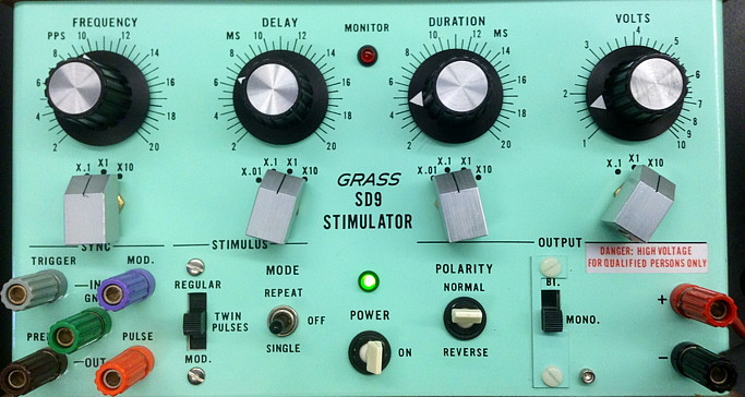
Stimulator controlsThe four controls on the top section of the stimulator's front panel
determine the Frequency of the stimuli (how often stimulus pulses are
produced), the Delay between the trigger pulse and the stimulus pulse, the
Duration (width) of the stimulus pulse, and the Volts (amplitude)
of the pulse. Each control has a black knob and a metal multiplier switch under it.
The setting depends on both of these knobs. For example, in this image, the delay
is set at 6.5 msec, and the duration is 0.45 msec. [Note that it is good practice when switching the multiplier to a higher range to first turn the black knob down to its minimum setting, and then switch the multiplier to the next range.]
The bottom section has a set of binding posts on the left; we will use the
prepulse and ground (gnd) connections to obtain a trigger pulse.
The stimulus is controlled by the Regular/Twin Pulses slide switch and
the Repeat/Off/Single switch. Polarity allows reversing which
stimulating connection is positive (start with Normal, where red is positive).
Use a Mono (monophasic) output pulse. The stimulus itself is produced at
the red and black binding posts at the right. |
Set the stimulator's voltage output to the x1 range, and adjust the vertical scale of the oscilloscope's CH2 initally to 5 volts per division (you can change it after you see how big the pulse will be). Turn the stimulator's power on (you can leave it on for the rest of the experiment), and set the series of switches across the bottom of the stimulator as follows:
- Stimulus: REGULAR
- Mode: REPEAT
- Polarity: NORMAL
- Output: MONO.
Set the oscilloscope's trigger source to External (Trigger menu), move the trigger point to early in the sweep, adjust the trigger level, and observe the stimulus pulses as you try out the functions of the stimulator's knobs and switches. The relationship between the synchronizing prepulse (which goes to the trigger circuit of the oscilloscope) and the stimulus pulses (which normally go to electrodes on the nerve) is shown in the following figure.
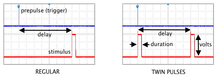
Also explore the Twin Pulses setting, which places one stimulus pulse after the normal delay and a second pulse at the time of the trigger pulse. Use a brief pulse Duration and an interpulse Delay of about 20 msec. (The oscilloscope sweep must be slow enough to see both of the twin pulses). Vary the Delay to see how the time between the pair of pulses changes.
Two points of caution:
(1) Do not use the MOD setting of the Stimulus switch, since it requires an external modulating signal that you are not providing.
(2) Do not have the values of Delay plus Duration exceed 50% of the time between pulses. The time between pulses is determined by the Frequency control. For example, at a frequency of 20 pulses per second, there are 50 msec between pulses. The pulse duration plus delay should not exceed 50% of this period, or 25 msec. If the duration were 1 msec, the delay should not be more than 24 msec.
When you restore connections to use for the rest of the experiment, you should leave the trigger settings as they are. You will need to:
- disconnect the stimulator's output terminals from the patch panel (you are finished with that cable),
- move the stimulator next to the baseplate,
- turn off the oscilloscope's CH2 and turn on CH1 if it is not already on, and
- check that the CH1 side of the patch panel is connected to the output of the DAM50 preamplifier (long red cable).
You should also reset the stimulator initially for
- regular (not twin) pulses,
- a low frequency,
- brief delay,
- brief duration, and
- low voltage.
You will later increase the voltage and/or duration as
you watch the nerve's response.
B. Dissection.
View the video: Action Potentials in Earthworm Giant Axons
Before beginning the dissection, make sure your dissecting kit contains a fine glass rod with a delicate point. Use the rod for probing or lifting the nerve cord. Do not pinch the cord with forceps.
Anesthesia. Obtain an earthworm and place it in the 10% ethanol solution to anesthetize it. Earthworm anesthesia is a problem: dilute alcohol acts very slowly, and often leaves a squiggling worm that is difficult to dissect, while concentrated alcohol "pickles" the outside of the worm, knocking out the responses of touch receptors and threatening the response of the giant fibers. Use the minimum anesthesia you can tolerate; it is really for you, not for the worm (which is too simple to care).
After suitable anesthesia, rinse the alcohol off the worm with tap water and allow the excess water to drain off. Pin out the worm dorsal side up on a flat dissecting dish placed on the stage of your microscope (check that the worm is in the field of view). Place pins only in the region of the worm where you intend to open an incision; for suction electrodes, an incision about two-thirds of the distance from the head to the tail works well. Insert the pins at very shallow angles so that they do not get in the way of your dissecting tools or (later) the electrode.
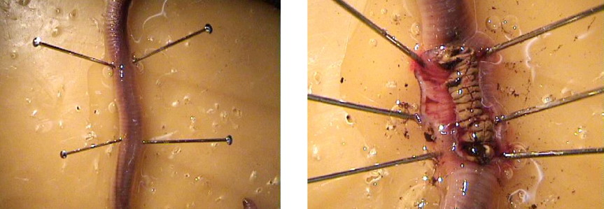
With forceps and scissors (not a scalpel), open an incision and extend it an inch or two, as shown above. Use the pins to keep the incision open, and flush out the body cavity from time to time with saline. The drawings below will help you identify the nerve cord and other internal structures. Keep the exposed nerve cord moist by tilting the dissecting dish so that saline pools at the incision. Use small blocks of tackiwax to support the dish in a tilted position.
Cut the nerve cord near the end of the incision farthest from the head, and free about a centimeter of the cord from its lateral and ventral connections until it is no longer attached to the body wall.
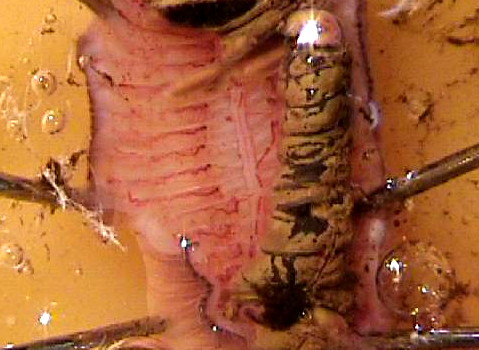
Place the recording electrode. Start by grounding
the preparation: clip one end of an alligator clip lead to
one of the dissecting pins (pick one that is out of the
way). Clip the other alligator clip to the white (ground)
binding post of the amplifier's input block. Then clamp a
suction
electrode in a micromanipulator (firmly!), attach its connections
to the amplifier's input block, and lower the
manipulator so that the tip of the electrode is in the saline near
the nerve cord. Gently draw some saline into the electrode; you need
to have a continuous column of saline (no bubbles!) that is long
enough to reach the electrode's internal wire (a few cm). The electrode's
external wire also needs to be in the saline pool. Position the tip of
the electrode against the cut end of the nerve cord, and gently draw the
nerve cord into the electrode. Turn
on your preamp and audio monitor, and you should hear and see some
spontaneous activity in (non-giant) axons.
C. Mechanical stimulation.
Touch or stroke the anterior end of the
worm with the blunt tip of your glass rod. Are there any
large spikes in response? These would be in the median giant. When you are
first exploring for spikes, you will find it helpful to change the
trigger menu's Source to CH 1 and adjust the trigger
Level knob so that the baseline noise itself triggers sweeps
(you can also force sweeps by changing the trigger menu's
Sweep setting to Auto). If you find spikes, readjust
the trigger Level knob so that large spikes trigger the
sweeps. Capture and save a screenshot
of one or two examples of the giant spikes (or of ordinary
spontaneous spikes if you don't elicit responses in the
giants).
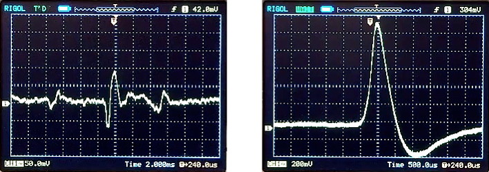
Left, spontaneous motor activity. Right, evoked action potential in median giant axon. Note the difference in vertical and horizontal (time) scales in the two figures; the giant spikes are almost ten times bigger than the spikes in ordinary axons.
If you are getting no responses from the giants after a
few minutes of exploration, go on immediately to the next
section.
D. Electrical stimulation
Connect two straight-pin electrodes to the output (red and black terminals) of a stimulator. Insert the electrodes across from each other through the body wall at the head end of the worm. The body surface and the dissecting dish must be dry near the stimulating electrodes, or the saline will "short out" the stimulus and reduce its effectiveness.
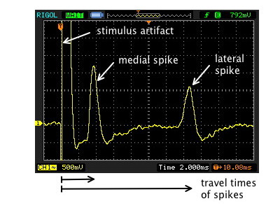
Check that the stimulus control is set to "Regular," not "Twin Pulse," and that the stimulator's delay is brief (1 or 2 msec). With the pulse rate at a frequency of several per second, a duration of 0.1 msec, and the voltage at its lowest setting, turn on the stimulus ("repeat"). If you changed the oscilloscope's trigger source to CH1 to see spikes elicited by stroking, you will need to return it to EXT source and readjust the trigger level (if necessary) until the stimulator is triggering the sweeps. Gradually increase the stimulus voltage. You may see a stimulus artifact that increases gradually as you increase the voltage. (The artifact represents stimulus current that has travelled to the recording electrode through the saline and the tissue fluids; it is not a biological response). When the stimulus reaches threshold, an action potential from one or both giant axons will suddenly appear.
Then do the following:
(1) Stop the sweep after capturing a good example of
an action potential in the giant axon(s).
Save the
screen image to a USB flashdrive, from which you can
transfer it to your computer later for inclusion in the
summary page you will make at the end of the afternoon.
From the screen, measure the action potential's duration and its apparent amplitude. (You can use the manual Cursor settings to make these measurements, or you can count divisions on the screen.) Divide by the amplification factor (gain) of the preamplifier, and obtain the real amplitude of the action potential at the electrodes.
For example, if the height of the action potential on the screen is 120 mV and the amplifier's gain is 1000x, then the potential at the electrodes was really 120/1000 mV, or 120 µV.
(2) Measure the conduction velocity in the giant axons. The conduction velocity is the distance between the stimulating electrodes and the recording electrode divided by the time it took the action potential to travel that distance. You can measure the travel time from the same image as in part (a).
The negative stimulating electrode actually initiates the action potential, since it is that electrode that decreases the potential between the (negative) inside of the axon and the (now also negative) fluid around the axon. The decrease in potential (depolarization) opens channels in the axon membrane and initiates the action potential. Reversing the stimulus-polarity switch reverses which of the stimulating electrodes is the negative one. For one of the polarities, the action potential may make a longer trip and take slightly longer to reach the recording electrode. You can see this effect, but you may need to readjust the stimulus voltage when you reverse the stimulus polarity. If there is a noticeable difference in conduction time, set the polarity to make the pin closest to the recording electrode the active stimulating electrode.
Use your ruler to measure the distance between the stimulating pin and the recording electrode. (You may need to estimate parts of the path if the worm is curved.) Measure the time on the screen between the stimulus artifact and each spike. Divide the distance (in mm) by the time (in msec) to find the conduction velocity (meters/second) of both the medial and the lateral giants' spikes.
(3) Measure and plot a strength-duration curve for the stimulus. Begin with the briefest stimulus duration that your stimulator can provide, and find and record the stimulus voltage that is just above threshold for one of the giant axons. Then double the stimulus duration, find the new threshold voltage for the same axon, and proceed in that way to measure the relation between duration and voltage. Keep doubling the stimulus duration until the threshold voltage stops changing.
Note that if the stimulus duration lasts so long that it overlaps the elicited spike, it does not make any sense to make it longer. The spike is already underway, and continuing to depolarize the axon cannot contribute to initiating a spike that is already underway.
Plot stimulus duration (x-axis) against threshold voltage (y-axis), using the graph paper on the back of the Lab4 checklist.
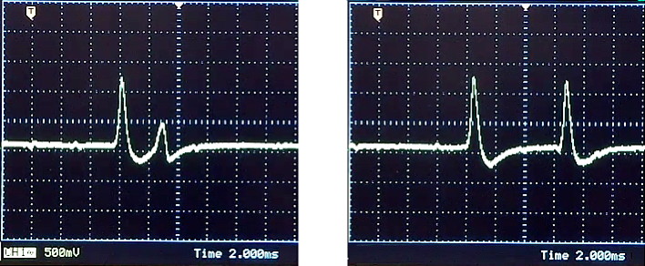
(4) Measure the refractory period that follows an action potential. Adjust the Delay control of the stimulator to about 20 msec. As you increase the delay, the stimulus artifact and the spike will move to the right on the screen.
The delay is the time between the prepulse sync pulse (which occurs at the trigger point for the sweep) and the actual stimulus pulse (which appears later, as the stimulus artifact).
Now switch the stimulus mode from "Regular" to "Twin Pulses." Two stimuli will now be delivered for each sweep, one pulse at the trigger point, and a second one at a later time governed by the delay control. If the second pulse occurs 10 or 20 msec after the first pulse, the axon will have fully recovered from its response to the first pulse.
Gradually decrease the delay between the two stimulus pulses, and observe the action potentials. When the second pulse is only a few msec later than the first, the axon will still be recovering from generating the previous action potential and will be somewhat refractory. The interval at which the second response first drops out marks the end of the refractory period, although the observed interval will depend on the strength of the stimulus. A stronger stimulus can force a second spike before the refractory period has fully ended.
You may also see the amplitude of the second action potential become smaller than normal as the delay is reduced, reflecting the elevated potassium-conductance and the large number of inactivated sodium channels that trail behind the first action potential. If you can, capture images of reduced and normal second spikes and save the screen images to your flashdrive. Two examples are shown here:
3. At the end of lab:
Post a single summary page that you make in Pages or Word showing:
- a screenshot of an evoked action potential from part (1),
- the conduction velocity you calculated in part (2),
- a screenshot of one or more traces showing the refractory period (part 4).
Also post the strength-duration curve that you plotted in part (3).
Make sure that the full names of all the lab partners are on both pages as authors.
Before you leave, rinse and dry your tools and dissecting dish. Turn off power to all equipment, including the stimulator and the DAM-50 preamplifier.
Links
Appendix: Capturing Oscilloscope Screenshots
Appendix: DAM 50 Preamplifier
© 2003, 2015 by Richard F. Olivo. Permission is granted to non-profit educational institutions to reproduce or adapt this Web page for internal use provided that the original source and copyright are acknowledged.