
Biological Sciences 300/301, Smith College | Neurophysiology
Lab 3: The Effect of Potassium Concentration
on the Resting Potential
http://www.science.smith.edu/departments/NeuroSci/courses/bio330/labs/L3rp.html
Bio 300/301 Home | Schedule | Videos | Laboratories | Administrative Information
View the videos Intracellular Recording from Crayfish Muscle Cells and Making Microelectrodes
1. Background.
Resting potential.
Muscle cells, like nerve cells, have resting potentials and respond electrically to appropriate stimuli. In this experiment, we will measure the resting potential of muscle cells in the crayfish abdomen with different concentrations of K+ in the bath. We use muscle cells rather than nerve cells because of their large size and the relative ease with which they can be impaled with microelectrodes.
A full discussion of resting potentials will be found in your textbook, and it would be helpful to read that section before doing this experiment. In brief, the equilibrium potential for any ion is the electrical potential across the membrane that exactly offsets the tendency of that ion to diffuse from regions of high to low concentration. For potassium ions in particular, there is a tendency to diffuse from inside the cell (where they are in high concentration) to the outside (where they are sparse). After a relatively few K+ ions have left the cell, however, the cell will have become negative enough inside so that K+ ions are attracted into the cell. The rates of entry (attracted by the negative interior) and of exit (diffusing from high to low concentration) will be exactly balanced at equilibrium. The potential that creates this equilibrium is (for K+, 20oC):
EK = 58 log Ko/ K i (Nernst equation)
where EK is the potential in mV, and Ko and Ki are the concentrations of K+ outside and inside the cell, respectively.
For nerve or muscle cells, the membrane potential at rest is very close to the potassium equilibrium potential. This occurs because the permeability to potassium is very much higher than the permeability to other ions at rest, and thus potassium ions cross the membrane most freely and establish their own equilibrium conditions. Proof of this can be obtained by altering the external potassium concentration. If the resting potential actually does shift to the new EK, as predicted by the Nernst equation, that shows that potassium ions establish the resting potential.


Crayfish abdominal musculature.
The crayfish abdomen ("tail") contains two classes of muscle: those that straighten the abdomen (extensors) and those that bend it (flexors). In addition, extensors and flexors each can be subdivided into rapidly contracting types (fast or phasic), such as the fast flexors that create the rapid tail flips in escape behavior, and slow or tonic types that carry out slower postural movements. In the crayfish abdomen, the slow muscles are arranged in thin superficial sheets on the ventral surface (the slow or superficial flexors) and on the dorsal surface (the slow or superficial extensors). The main bulk of the muscle in the abdomen is composed of the fast muscles: the deep flexors and deep extensors. We will record only from the median (inner) deep extensors, which appear as a spiral bundle near the midline. The accompanying photo and diagram show the locations of these muscles as they will appear in your dissected preparation.
Click small figures to see larger versions.
2. Procedure.
The methods for this experiment are adapted from H. Atwood & I. Parnas (1968), "Recording from the crayfish abdominal extensor muscle preparation with microelectrodes." (In: G. A. Kerkut, editor, Experiments in Physiology and Biochemistry, Vol. 1, Chapter 16.)
Saline solutions.
The class will be provided with two saline solutions for crayfish, the normal van Harreveld's solution and a high-potassium solution. Intermediate concentrations of K+ can be made by mixing measured volumes of the two solutions.
|
Normal (5.4 mM K+) |
High K (60 mM K+) |
|
|
NaCl |
12.0 g/liter |
8.87 g/liter |
|
KCl |
0.4 |
4.42 |
|
CaCl2 |
1.5 |
1.5 |
|
MgCl2 . 6H20 |
0.5 |
0.5 |
|
NaHC03 |
0.17 |
0.17 |
We will pool class data for the experiment, and so we will all use the same set of K+ concentrations. A "solutions committee" (one member from each group) will make three appropriate intermediate mixtures between the two stock solutions (five test concentrations in all). For example, 2 volumes of the normal saline and 1 volume of the high-K saline gives 3 volumes of a solution containing 23.5 mM K+. The intermediate concentrations should be spaced evenly on the logarithmic x-axis on which you will plot your data and not be all bunched up at one end or the other (see semilog graph paper to view or print as PDF). At the end of the experiment, in addition to plotting your own data by hand, we will ask for a few volunteers to plot the class's grouped data.
Arranging the equipment.
Your setup will have many new items of equipment this week, which are labelled in this figure. The equipment includes:
- a baseplate, grounded to the equipment rack
- a dissecting microscope
- a micromanipulator to hold the electrode and the input probe of the amplifier
- a voltage follower amplifier, described below
- a fiber optics light on a stand
- a vacuum aspirator to remove solutions from around the preparation
- a dissecting dish, pins, and a dissecting kit with scissors and fine forceps

To record intracellular potentials, we use glass micropipettes filled with 3M KCl, which have a very high resistance. To prevent the intracellular potential from being lost across the electrode, we need an amplifier with a very high input resistance, as we discussed in an earlier lab. We use "voltage followers," amplifiers that in this case have a gain of one. The voltage followers have their electronics in a cylindrical probe that we mount directly on the micromanipulator, close to the electrode. This helps minimize the pick-up of electrical noise. A delicate silver wire attached to the probe will be inserted into the top of the microelectrode, to make contact with the 3M KCl. You can see the arrangement of the electrode, the probe, and the dish in a close-up photo.
The reference (ground) electrode is a clip lead from the probe, which will normally be clipped to a stout silver wire immersed in the dissecting dish's bathing solution. Keep the clip itself out of the bath, or you will make a battery of two dissimilar metals and a saline solution.
Connect the output of the voltage follower by a bnc/bnc cable to channel 1 of the oscilloscope. Set the oscilloscope to display channel 1, making sure channel 1's input is set on DC (these are steady potentials, and they would be filtered out by an AC input setting). Choose a horizontal scale of 50 ms/div. (If you prefer, you can also do the experiment using a very slow sweep. This will show you any slow drift in the potentials you record, but this isn't recommended to start with.) Set the trigger point near the left edge of the display, using the horizontal position control, and from the Trigger menu set the Sweep to Auto triggering. In the Acquire menu, select Normal, not PeakDetect, and in the Display menu, make sure Persist is Off.
Dissection.
The dissection is very simple and fast. Cut the abdomen (tail) from a crayfish, and then cut along the abdomen on each side just above the little indentations on each segment (see the photos and the video for the placement of these cuts).


Using your fingers, tear the upper (dorsal) part of the abdomen (the part you will keep) from the much larger lower musculature and swimmerets. The dorsal extensor muscles usually separate cleanly from the large ventral mass of flexor muscles.


Place the small dorsal section of abdomen immediately into normal saline in your dissecting dish. Pin the section at its anterior and posterior ends to hold it firmly with the extensor muscles visible. Angle the pins outward to keep them out of the way of the microelectrode.
The preparation should remain in good condition for at least one or two hours.

Position the dissecting dish on the microscope stage so that you can see the muscles you intend to impale, even when you have zoomed-in at high power. The saline solution should cover the muscles, but if the solution is very deep, it becomes hard to see the microelectrode tip as it impales the muscle. Looking through the microscope, tear away any stray connective tissue (and the green intestine, if it is there) using your fine forceps. You should be able to see the spiral muscle bundles without any obstacles in the way.
Clamp the micromanipulator so that it is in the middle of its movement ranges, and so an electrode mounted at a slight tilt would be in the microscope's field of view. When the dish, microscope, and manipulator are all where you want them, use marble-sized bits of tackiwax (side counter) to attach the microscope to the baseplate, and the dissecting dish to the microscope stage. Arrange the fiber-optics light pipe so the muscles are illuminated from the side, which helps you see their three-dimensional shape.
Be sure the manipulator is clamped very firmly. You do not want anything to bounce when an electrode is in place, or the impalement will be lost and the tip will be broken.
Connect the reference clip lead to the silver wire in the bath, where it will remain for the rest of the experiment.
View the video Making Microelectrodes

The microelectrodes are kept in Coplin jars on the bench top, to be shared by two facing groups. Each jar has more than enough electrodes for the entire afternoon. If you break some early in the experiment, you will still probably be able to use one microelectrode for most of the day. When you do change electrodes, you must be careful to replace the slide of electrodes TIPS DOWN soon after you have removed an electrode for use, or the others will all be spoiled. To remove an electrode from the slide, use forceps to gently angle one electrode away from its neighbors, and then ease it out from under the rubber band that holds it. (Do not do this until you are ready to use the electrode.)
Place the top of the electrode gently onto the bit of tackiwax at the end of the electrode holder. You do not need to bury it in wax, since anything that dislodges a gently attached electrode will be likely to break the tip. Insert the probe's input wire into the electrode so that it makes good contact with the KCl (one or two cm should be enough). Lower the electrode's tip into the bathing solution while you observe from the side.
Zero the voltage follower's output
Turn on the voltage follower and use its position control to try to move the trace to the oscilloscope's zero baseline. Note that the position control is either a multi-turn knob, or a dual-function knob with both a coarse and a fine control on the same shaft. We want the output of the voltage follower to report 0 volts when the electrode tip is in the bath.
However, we sometimes have trouble making the voltage follower's output equal 0 volts (possibly due to some battery-like interactions between the metal electrodes and the saline). In that case, use the oscilloscope's vertical position control to put the trace on a convenient grid line. Choose a grid line high on the screen, since you expect the electrode to report a negative potential when it impales a cell. Once you have established the trace at a convenient grid line, increase the vertical scale to 10 or 20 mV/division. (You are almost ready to impale a cell.)
Cursors: If you wish, turn on the vertical (Y) cursors and position Cursor A over the trace, to mark the baseline potential (zero volts) that the electrode detects in the bath. Turn off Cursor A and activate Cursor B, which you can move to the new position of the trace after each impalement. Cursor A marks the zero potential (the bath), while Cursor B marks the impaled potential (the cytoplasm). The difference between Cursors A and B is the resting potential.
Raise the electrode tip out of the bath and position it over a group of muscle cells. The oscilloscope trace will disappear off the screen temporarily, until you re-establish a complete circuit by dipping the microelectrode's tip into the bath.
.

Recording the resting potential.
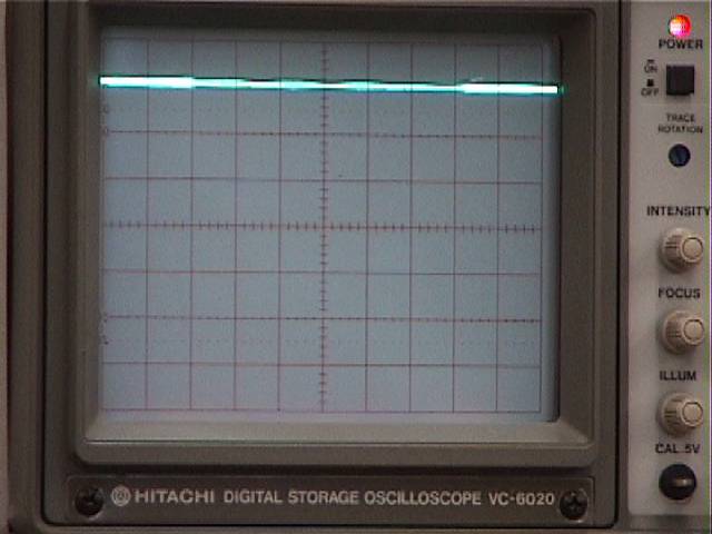
With the electrode tip positioned in the saline over a muscle cell, and while you look through the microscope, slowly lower the electrode using the manipulator's coarse vertical control. Your lab partner should watch the oscilloscope screen. If necessary, when the electrode is in the bath, re-zero the trace near the top of the screen (upper photo), as described above. (Throughout the experiment, readjust the zero level with the voltage follower's position control whenever the electrode is in the saline, prior to an impalement.)
When you see the muscle cell indent under the electrode tip prior to impalement, your partner will see the trace move a little and then drop suddenly when impalement occurs (lower photo). Sometimes tapping the manipulator can help an electrode puncture the connective tissue around a muscle cell and penetrate the cell membrane. Make sure the impalement is a firm one -- the trace should not be drifting up and down. Slightly advancing the electrode can seal up the puncture and reveal the full intracellular potential, but advancing too far will push the tip out of the other side of the cell. The best penetrations are ones that appear very abruptly, without a slow drift to the final level.
Write down the resting potential after it stabilizes. Obtain readings from at least four or five cells (make sure you are impaling different cells, and not just the same one over and over). Avoid damaged cells. They will be depolarized and give abnormally small resting potentials due to ions entering through the torn membranes.
Plot the data as you go along on semilog paper. In laying out the vertical axis, remember that resting potentials are negative numbers, and it is customary to plot negative downwards. Put zero volts at the top of the vertical axis. Plot all of the points you obtain at each concentration. You can later judge if one or more is an outlier, possibly from a damaged cell. When you report your results for each solution on the blackboard, drop any outliers and provide the average resting potential for the remaining points.
Keep an organized table of the raw potentials and the concentrations.
Proceed to the next solution. Work from low K+ concentrations (normal saline) to high concentrations. Aspirate out the saline, pour in a small amount of the new solution as a rinse, aspirate that out, and then pour in an adequate amount of the new solution. Allow the preparation to soak for 5 to 10 minutes in the new solution. Record resting potentials from four or five nearby cells, and then move on to the next concentration.
3. Plotting data.
At the end of the afternoon, after you have taken samples of resting potentials in each solution, your team should have created a plot of its own raw data and posted its average data for each solution on the blackboard.
Draw a best-fit straight line through your raw data. Problem: How could you use that line to estimate the internal concentration of K+ in these cells? (Hint: what would the equilibrium potential be if the external K+ concentration were the same as the internal concentration?)
Before you leave the laboratory, post your graph (with your team's names on it) on the bulletin board.
© 2003, 2008, 2009 by Richard F. Olivo. Permission is granted to non-profit educational institutions to reproduce or adapt this Web page for internal use provided that the original source and copyright are acknowledged.