Electrical power is a little bit like the air you breathe: You don't
really think about it until it is missing. Power is just "there,"
meeting your every need, constantly. It is only during a power failure,
when you walk into a dark room and instinctively hit the useless light
switch, that you realize how important power is in your daily life. You
use it for heating, cooling, cooking, refrigeration,
light, sound, computation, entertainment... Without it, life can get somewhat cumbersome.
Power travels from the power plant to your house through an amazing system called the power distribution grid.
The grid is quite public -- if you live in a suburban or rural area,
chances are it is right out in the open for all to see. It is so
public, in fact, that you probably don't even notice it anymore. Your brain
likely ignores all of the power lines because it has seen them so
often. In this article, we will look at all of the equipment that
brings electrical power to your home. The next time you look at the
power grid, you will be able to really see it and understand what is
going on!
The Power Plant
Electrical power starts at the power plant. In almost all cases, the power plant consists of a spinning electrical generator. Something has to spin that generator -- it might be a water wheel in a hydroelectric dam, a large diesel engine or a gas turbine. But in most cases, the thing spinning the generator is a steam turbine. The steam might be created by burning coal, oil or natural gas. Or the steam may come from a nuclear reactor like this one at the Shearon Harris nuclear power plant near Raleigh, North Carolina:
No matter what it is that spins the generator, commercial electrical generators of any size generate what is called 3-phase AC power. To understand 3-phase AC power, it is helpful to understand single-phase power first.
The Power Plant: Alternating Current
Single-phase power is what you have in your house. You generally
talk about household electrical service as single-phase, 120-volt AC
service. If you use an oscilloscope
and look at the power found at a normal wall-plate outlet in your
house, what you will find is that the power at the wall plate looks
like a sine wave, and that wave oscillates between -170 volts
and 170 volts (the peaks are indeed at 170 volts; it is the effective
(rms) voltage that is 120 volts). The rate of oscillation for the sine
wave is 60 cycles per second. Oscillating power like this is generally
referred to as AC, or alternating current. The alternative to AC is DC, or direct current. Batteries
produce DC: A steady stream of electrons flows in one direction only,
from the negative to the positive terminal of the battery.
AC has at least three advantages over DC in a power distribution grid:
- Large electrical generators happen to generate AC naturally, so conversion to DC would involve an extra step.
- Transformers must have alternating current to operate, and we will see that the power distribution grid depends on transformers.
- It is easy to convert AC to DC but expensive to convert DC to
AC, so if you were going to pick one or the other AC would be the
better choice.
The power plant, therefore, produces AC. On the next page,
you'll learn about the AC power produced at the power plant. Most
notably, it is produced in three phases.
The Power Plant: Three-phase Power
The power plant produces three different phases of AC power simultaneously, and the three phases are offset 120 degrees from each other. There are four wires coming out of every power plant: the three phases plus a neutral or ground common to all three. If you were to look at the three phases on a graph, they would look like this relative to ground:
There is nothing magical about three-phase power. It is simply three single phases synchronized and offset by 120 degrees.
Why three phases? Why not one or two or four? In 1-phase and
2-phase power, there are 120 moments per second when a sine wave is
crossing zero volts. In 3-phase power, at any given moment one of the
three phases is nearing a peak. High-power 3-phase motors (used in
industrial applications) and things like 3-phase welding equipment
therefore have even power output. Four phases would not significantly
improve things but would add a fourth wire, so 3-phase is the natural
settling point.
And what about this "ground," as mentioned above? The power
company essentially uses the earth as one of the wires in the power
system. The earth is a pretty good conductor and it is huge, so it
makes a good return path for electrons. (Car manufacturers do something
similar; they use the metal body of the car as one of the wires in the
car's electrical system and attach the negative pole of the battery to
the car's body.) "Ground" in the power distribution grid is literally
"the ground" that's all around you when you are walking outside. It is
the dirt, rocks, groundwater, etc., of the earth.
Transmission Substation
The three-phase power leaves the generator and enters a transmission substation at the power plant. This substation uses large transformers to convert the generator's voltage
(which is at the thousands of volts level) up to extremely high
voltages for long-distance transmission on the transmission grid.
A typical substation at a power plant
|
You can see at the back several three-wire towers leaving the
substation. Typical voltages for long distance transmission are in the
range of 155,000 to 765,000 volts in order to reduce line losses. A
typical maximum transmission distance is about 300 miles (483 km).
High-voltage transmission lines are quite obvious when you see them.
They are normally made of huge steel towers like this:
All power towers like this have three wires for the three
phases. Many towers, like the ones shown above, have extra wires
running along the tops of the towers. These are ground wires and are
there primarily in an attempt to attract lightning.
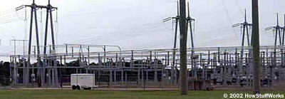
The Distribution Grid
For power to be useful in a home or business, it comes off the transmission grid and is stepped-down
to the distribution grid. This may happen in several phases. The place
where the conversion from "transmission" to "distribution" occurs is in
a power substation. A power substation typically does two or three things:
- It has transformers that step transmission voltages (in the tens or
hundreds of thousands of volts range) down to distribution voltages
(typically less than 10,000 volts).
- It has a "bus" that can split the distribution power off in multiple directions.
- It often has circuit breakers and switches so that the
substation can be disconnected from the transmission grid or separate
distribution lines can be disconnected from the substation when
necessary.
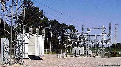
A typical small substation
|
The box in the foreground is a large transformer. To its left
(and out of the frame but shown in the next shot) are the incoming
power from the transmission grid and a set of switches for the incoming
power. Toward the right is a distribution bus plus three voltage
regulators.
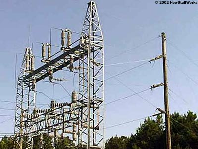
The transmission lines entering the substation and passing through the switch tower
|
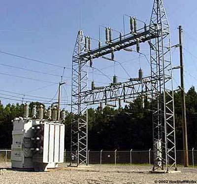
The switch tower and the main transformer
|
Now the distribution bus comes into the picture.
Distribution Bus
The power goes from the transformer to the distribution bus:
In this case, the bus distributes power to two separate sets of
distribution lines at two different voltages. The smaller transformers
attached to the bus are stepping the power down to standard line
voltage (usually 7,200 volts) for one set of lines, while power leaves
in the other direction at the higher voltage of the main transformer.
The power leaves this substation in two sets of three wires, each
headed down the road in a different direction:
The wires between these two poles are "guy wires" for support. They carry no current.
|
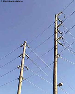
The next time you are driving down the road, you can
look at the power lines in a completely different light. In the typical
scene pictured on the right, the three wires at the top of the poles
are the three wires for the 3-phase power. The fourth wire lower on the
poles is the ground wire. In some cases there will be additional wires,
typically phone or cable TV lines riding on the same poles.
As mentioned above, this particular substation produces two different
voltages. The wires at the higher voltage need to be stepped down
again, which will often happen at another substation or in small
transformers somewhere down the line. For example, you will often see a
large green box (perhaps 6 feet/1.8 meters on a side) near the entrance
to a subdivision. It is performing the step-down function for the
subdivision.
Regulator Bank
You will also
find regulator banks located along the line, either underground or in
the air. They regulate the voltage on the line to prevent undervoltage
and overvoltage conditions.
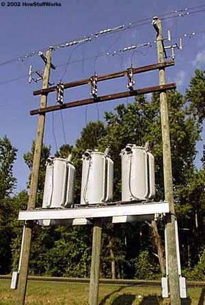
A typical regulator bank
|
Up toward the top are three switches that allow this regulator bank to be disconnected for maintenance when necessary:
At
this point, we have typical line voltage at something like 7,200 volts
running through the neighborhood on three wires (with a fourth ground
wire lower on the pole):
Taps
A house needs only one of the three phases, so typically you will see three wires running down a main road, and taps
for one or two of the phases running off on side streets. Pictured
below is a 3-phase to 2-phase tap, with the two phases running off to
the right:
Here is a 2-phase to 1-phase tap, with the single phase running out to the right:
At the House
And finally we
are down to the wire that brings power to your house! Past a typical
house runs a set of poles with one phase of power (at 7,200 volts)
and a ground wire (although sometimes there will be two or three phases
on the pole, depending on where the house is located in the
distribution grid). At each house, there is a transformer drum attached to the pole, like this:
In many suburban neighborhoods, the distribution lines are underground and there are green transformer boxes at every house or two.
Here is some detail on what is going on at the pole:
The transformer's job is to reduce the 7,200 volts down to the 240 volts
that makes up normal household electrical service. Let's look at this
pole one more time, from the bottom, to see what is going on:
There are two things to notice in this picture:
- There is a bare wire running down the pole.
This is a grounding
wire. Every utility pole on the planet has one. If you ever watch the
power company install a new pole, you will see that the end of that
bare wire is stapled in a coil to the base of the pole and therefore is
in direct contact with the earth, running 6 to 10 feet (1.8 to 3 m)
underground. It is a good, solid ground connection. If you examine a
pole carefully, you will see that the ground wire running between poles
(and often the guy wires) are attached to this direct connection to
ground.
- There are two wires running out of the transformer and three wires running to the house.
The
two from the transformer are insulated, and the third one is bare. The
bare wire is the ground wire. The two insulated wires each carry 120
volts, but they are 180 degrees out of phase so the difference between
them is 240 volts. This arrangement allows a homeowner to use both
120-volt and 240-volt appliances. The transformer is wired in this sort
of configuration:
|
The 240 volts enters your house through a typical watt-hour meter like this one:
The meter lets the power company charge you for putting up all of these wires.
Safety Devices: Fuses
Fuses and circuit breakers are safety devices.
Let's say that you did not have fuses or circuit breakers in your house
and something "went wrong." What could possibly go wrong? Here are some
examples:
- A fan motor burns out a bearing, seizes, overheats and melts, causing a direct connection between power and ground.
- A wire comes loose in a lamp and directly connects power to ground.
- A mouse chews through the insulation in a wire and directly connects power to ground.
- Someone accidentally vacuums up a lamp wire with the vacuum cleaner, cutting it in the process and directly connecting power to ground.
- A person is hanging a picture in the living room and the nail
used for said picture happens to puncture a power line in the wall,
directly connecting power to ground.
When a 120-volt power line connects directly to ground,
its goal in life is to pump as much electricity as possible through the
connection. Either the device or the wire in the wall will burst into
flames in such a situation. (The wire in the wall will get hot like the
element in an electric oven gets hot, which is to say very hot!). A fuse
is a simple device designed to overheat and burn out extremely rapidly
in such a situation. In a fuse, a thin piece of foil or wire quickly
vaporizes when an overload of current runs through it. This kills the
power to the wire immediately, protecting it from overheating. Fuses
must be replaced each time they burn out. A circuit breaker uses the heat from an overload to trip a switch, and circuit breakers are therefore resettable.
The power then enters the home through a typical circuit breaker panel like the one above.
Safety Devices: Circuit Breakers
Inside the circuit breaker panel (right) you can see the two primary wires from the transformer entering the main circuit breaker
at the top. The main breaker lets you cut power to the entire panel
when necessary. Within this overall setup, all of the wires for the
different outlets and lights in the house each have a separate circuit
breaker or fuse:
If the circuit breaker is on, then power flows through the wire
in the wall and makes its way eventually to its final destination, the outlet.
What an unbelievable story! It took all of that equipment to get power from the power plant to the light in your bedroom.
The next time you drive down the road and look at the power lines, or
the next time you flip on a light, you'll hopefully have a much better
understanding of what is going on. The power distribution grid is truly
an incredible system.