![]() CSC270 Lab #1
CSC270 Lab #1
EXPERIMENT 1: Investigating the Digital Training Kit
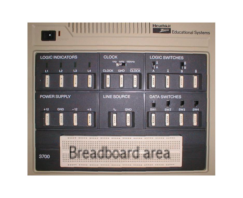
We will be using the horizontal part of the kit in the first few labs. The goal for now is to get a sense of how the different parts operate.
With your partner, going at your own pace, follow the steps outlined below.
|
You will now run some simple experiments with the clock circuitry, and in particular the clock signal. The clock signal will be useful when we move from combinational circuits (first quarter of the course) to sequential circuits (second quarter).
|
EXPERIMENT 2:
A simple priority-encoder circuits.
In this part you will wire up a simple circuit corresponding to the priority encoder we saw this morning in class. Make sure you follow the rules for good wiring as you go along (highlighted in red in the text below). More information and details will be given out during the lab.
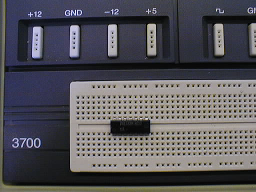 |
Put the circuit (which we will sometimes refer to as chip, or IC--short for integrated circuit) with the designation 74LS32 on the breadboard area of the kit, with the notch to your left (in other words, you should be able to read the markings on the chip without problems). Make sure it sits over the middle groove. (You can right click on the pictures and select "View Image" to see the full size photo) |
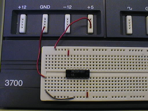 |
Add wires as shown in the picture to the left. When wiring circuits up, always use short wires if possible, so as to avoid huge loops and spaghetti-type results. |
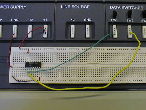 |
Then add wires between two switches and the chip. |
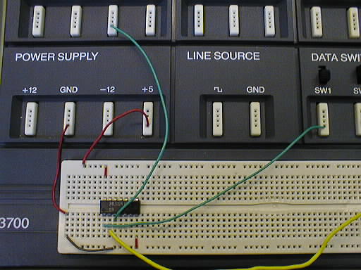 |
Then a wire between the chip and a logic indicator. |
A report should be a log of your work, not an idealized version of it.
 To
view in a separate window, full scale, click here.
To
view in a separate window, full scale, click here.