
Biological Sciences 330, Smith College
| Research in Cellular Neurophysiology
Rigol Digital Oscilloscope
revised: February 21, 2019
Rigol DS1022C Digital
Oscilloscope
|
Click
links for |
|
||||

Screen Display
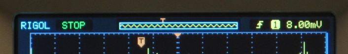
From left to right, the text and symbols at the top edge of the screen show:
- RIGOL, the manufacturer's name.
- "STOP," indicating that the display has been frozen with the RUN/STOP button. This might instead say "WAIT," indicating that the trigger circuits are waiting for an appropriate signal before a new sweep is stored, or "T'D" indicating that the sweep has been triggered.
- Memory usage: the blue box represents the total memory available to store signals, and the jagged yellow line shows how much of that memory is displayed on the screen. In this image, all of the memory is displayed. The small orange "T" indicates the location of the trigger point within the total stored data. The black T in an orange box in the screen grid also shows the location of the trigger point.
- Trigger slope, represented here by the upward arrow (positive slope).
- Trigger source, in this case Channel 1.
- Trigger level, here (+) 8.00 mV.
back to overview of oscilloscope panels
The grid in the middle of the screen is where voltage (vertical) is plotted against time (horizontal). Two parallel plots are made, one for the voltage signal on channel 1 (CH1, yellow) and one for the voltage signal on channel 2 (CH2, blue).
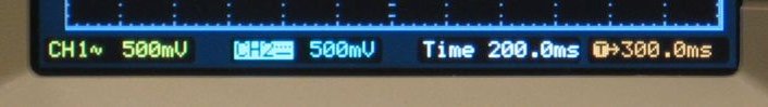
From left to right, the bottom edge of the screen shows:
- CH1: Channel 1 is "AC coupled," indicated by the squiggle. This is the coupling for displaying rapdily changing signals.
- Channel 1's vertical sensitivity is 500 mV per division. Note the color coding: the trace and labels for Channel 1 are yellow.
- CH2: Channel 2 (blue color) is "DC coupled" (dashed and solid parallel lines). This is the setting for displaying steady or slowly changing signals.
- Channel 2's vertical sensitivity is also set at 500 mV per vertical division. The highlighted box on "CH2" indicates that it is the channel that is currently controlled by the vertical sensitivity and position knobs. Pressing the green button for CH1 would instead make Channel 1 the actively controlled channel.
- Time is the sweep speed (horizontal scale), 200.0 ms (200 milliseconds per horizontal division).
- T (in orange) indicates that the trigger point is 300 ms before the center of the screen.
Menu Buttons
|
|
Many functions are controlled by menus that appear at the right edge of the screen. Selections from those menus are made with the five gray buttons just to the right of the screen, and a tan-colored selector knob that is at the top right of this photo, just below the illuminated circular arrow. In this example, the menu for channel 1 has been invoked by pressing the green CH 1 button. The menu has a number of choices, beginning at the top with "Coupling." By pressing the topmost gray button (opposite the "Coupling" label), a submenu has appeared (DC, AC, GND). The coupling is currently set at "DC" as shown by the highlighted "DC" in the submenu.
Turning the selector knob would allow selecting AC or GND coupling instead. Pressing the selector knob will register the choice. The menu can be dismissed by pressing the small round "MENU ON/OFF" button above the gray buttons. |


Vertical Controls
|
|
In the VERTICAL box, the two top buttons on the left (CH1, CH2) turn channels 1 and 2 on or off, make a channel the active one for the vertical controls, and bring up the menu for that channel's settings. The two remaining buttons, MATH
and REF, are for features we will not
use. The POSITION knob adjusts the vertical position of whichever trace is currently the active one. (Pressing the CH1 or CH2 button makes that channel the active one.) Pressing the position
knob places the active channel's zero-volts level
at the vertical middle of the screen, useful for
finding a trace that has been positioned
off-screen. Turning the SCALE knob changes the vertical sensitivity (volts/division) of the active channel. The value of the setting is shown at the bottom left of the screen. Pressing the scale knob changes the steps from major steps (1, 2, 5 sequence) to very fine steps, a feature that we will not use. Pressing the knob again restores the standard 1, 2, 5 sequence. |

Horizontal Controls
|
|
The horizontal POSITION knob adjusts the trigger point, indicated by the black T in an orange arrow at the top of the grid, and an orange T in the picture of memory above the grid. (Note that if the screen displays only part of the total memory, the trigger point can be located off the screen. The orange arrow surrounding the T will point off the screen to indicate this.) Pressing the position knob places the trigger point at the horizontal center of the screen.
The horizontal MENU provides functions that we will not use.
The horizontal SCALE knob sets the time represented by each horizontal box on the screen. Turning this knob will make a signal appear squeezed together (each box represents a longer period of time) or stretched out (each box represents a briefer interval of time). The time setting is shown by white numbers below the screen, which represent the value of each box in seconds (s), milliseconds (ms), microseconds (us), or nanoseconds (ns). We will generally work in the ms range, and never in the us or ns range. Pressing the scale knob creates a split-screen display, for looking at a full sweep plus an enlarged view of the middle of the screen. Engineers may find this useful, but we won't. |

Trigger Controls
|
|
The trigger point represents the moment in time when a signal first meets a set of criteria that the user selects. A typical trigger point for us would be the moment when an action potential is part-way up its rising phase. By selecting an appropriate set of criteria, each successive sweep will display new action potentials at the same place on the screen, allowing us to see their shape more easily than if they appeared at various random locations in successive sweeps. The trigger criteria are selected by: the LEVEL knob, which sets the voltage (height) that the signal must pass through. The trigger voltage can be positive or negative. Pressing the LEVEL knob sets the trigger level to 0 volts, from which it can be adjusted up or down. the trigger MENU, which allows us to set the Mode (we will always select Edge) 50% button forces the trigger level to half the height of a repetitive signal (not usually useful to us). FORCE displays a new sweep whether or not the trigger criteria have been met. This is useful if you are wondering why you are not seeing new sweeps. The top right of the screen shows the trigger slope, source and level as well as the location of the trigger point in memory and on the grid; the bottom right shows the horizontal trigger point (0 is the horizontal center of the screen; positive numbers are to the left of center, negative to the right). |

Run/Stop Button
|
|
RUN: the screen displays new data as they arrive. STOP: the screen freezes the last collected sweep. Pressing STOP again switches back to RUN mode. Single triggered sweeps automatically enter the STOP mode; pressing the RUN button activates the next single sweep.
|

 The
AUTO button will try to set the optimal
vertical and horizontal sensitivities for your
signal. Don't be tempted! AUTO was designed for
engineers, not neuroscientists, and it will give
you a close-up view of the electronic noise in the
baseline, which you will regret. Trust me, don't
press the AUTO button!
The
AUTO button will try to set the optimal
vertical and horizontal sensitivities for your
signal. Don't be tempted! AUTO was designed for
engineers, not neuroscientists, and it will give
you a close-up view of the electronic noise in the
baseline, which you will regret. Trust me, don't
press the AUTO button!Menu Area
|
|
Measure displays numerical measures of precisely repetitive signals, but it will not be useful to us. Acquire The first submenu selects between: Normal: each sample is displayed as a point on the screen Storage captures screenshots on a USB drive. Cursor measures differences in voltage or time between cursors that we set. Display selects dots or vectors, grid type, brightness, and persistence. Utility has preference settings we will not need. |

Input Connectors
|
BNC connectors ("Bayonet Neill-Concelman") are round connectors used for coaxial cables -- cables where an insulated wire carrying the signal is surrounded by a braided metal shield, which is in turn surrounded by a plastic coating. |
Female BNC connectors for channels 1 and 2 and the external trigger circuit are located along the bottom edge of the oscilloscope. In our lab, green and blue BNC cables will normally connect the oscilloscope to a patch panel, which is where we will connect cables from amplifiers and other signal sources. The empty EXT TRIG connector shows the structure of a BNC jack: an outer metal ring makes a ground (baseline) connection to the BNC plug, a central metal receptacle for a pin makes the "live" signal connection, and a white plastic insulator sits between them. The pins at the right edge
provide a 3-volt calibration signal for testing the
oscilloscope. |
